Micro-CT Bar Pattern Phantoms

For the determination of in-plane and axial spatial resolution

  • Evaluate axial and sagittal spatial resolution in preclinical and industrial micro-CT
  • Provides high resolution contrast
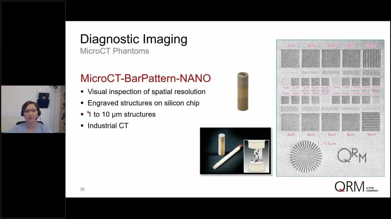
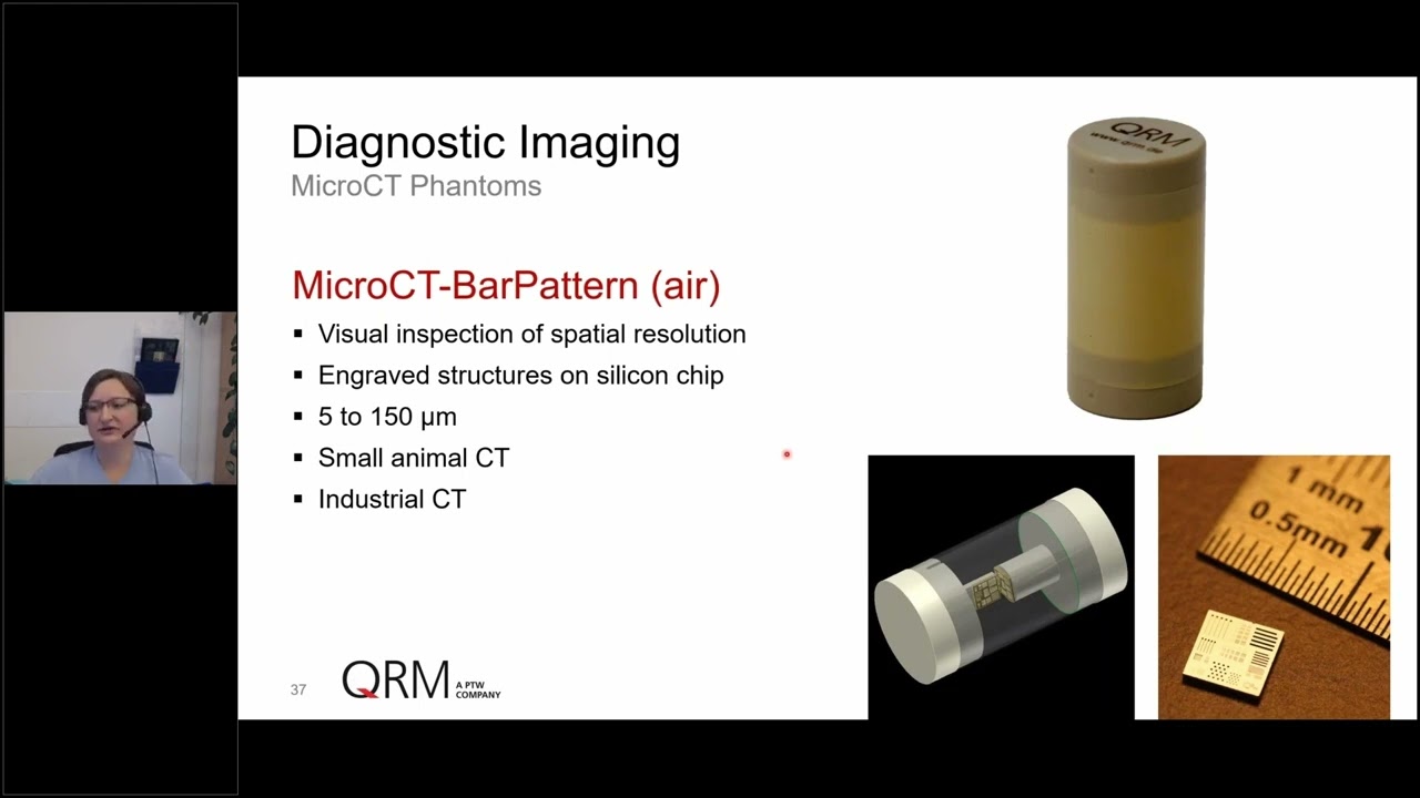
  • Bar and point structures down to 5 microns (air, QRM-70113 and resin, QRM-70114) or to 1 micron (NANO, QRM-70119)
  • Corresponds to 3.3 to 100 lp /mm (air, QRM-70113 and resin, QRM-70114) or 500 to 50 lp/mm (NANO, QRM-70119)


The Micro-CT Bar Pattern Phantoms are used to assess the spatial resolution in micro-CT in a direct visual manner. The phantoms offer an alternative to indirect methods for the evaluation of spatial resolution in high-resolution X-ray imaging modalities.

The phantoms contain of two chips, one orientated axial and one oriented in perpendicular (sagittal) to it. The chips are mounted on a slim support in air (QRM-70113, QRM-70119) or embedded within a resin cylinder (QRM-70114). The optimized arrangement of the different bar and point structures allows for the evaluation of spatial resolution in the center as well as in the periphery of the image in one single measurement.

QRM-70113, QRM-70114: The 5 mm x 5 mm chips contain bar and point patterns ranging from 5 to 150 microns (i.e. 100 to 3.3 lp / mm). The depth of the structures varies between 70 and 150 microns.

QRM-70119: The 3 mm x 3 mm chips contain bar and point patterns ranging from 1 to 10 microns (i.e. 500 to 50 lp / mm). The depth of the structures varies between 5 and 15 microns. In addition, a slanted edge and a so-called Siemens-star (actinomorphic star) are placed on the chip.

Other dimensions of housing are available upon request.


Micro-CT Bar Pattern Air, QRM-70113
Micro-CT Bar Pattern Resin, QRM-70114
Micro-CT Bar Pattern NANO, QRM-70119

Micro-CT Bar Pattern Phantom, air          
Phantom diameter: 20 mm        
Phantom height: 40 mm        
Phantom wall thickness: 0.2 mm        
Phantom material: air / plastic        
Contrast of pattern: silicon / air        
           
Micro-CT Bar Pattern Phantom, resin          
Phantom diameter: 8 mm        
Phantom height: 40 mm        
Phantom material: resin        
Contrast of pattern: silicon / resin        
           
Chip dimension: 5 mm x 5 mm        
Chip height: 0.66 mm        
Chip material: Silicon        
Range of the bar and point structures on the chip (width): 5 - 150 microns (see Table 1, Table 2)        
Range of the bar and point structures on the chip (depth): 70 - 150 microns        
Resolution: 100 to 3.3 lp/mm (see Table 1)        
           
Table 1:          
linewidth (microns) linepairs / mm        
5 100        
10 50        
15 33.3        
20 25        
25 20        
30 16.7        
50 10        
100 5        
150 3.3        
           
Table 2:number of lines and dots per section          
section line width (µm) lines per pattern dots (µm) dots per pattern  
A 5, 10, 25, 50, 100, 150 5 - -  
B 5, 10, 15, 20, 25, 30 5 5, 10, 15, 20, 25, 30 18  
C 5, 10, 15, 20, 25, 30 5 5, 10, 15, 20, 25, 30 18  
D -   5, 10, 25, 50, 100, 150 18  
E 5, 10, 25, 50, 100, 150 5 - -  
Phantom diameter: 5.4 mm      
Phantom height: 19 mm      
Phantom wall thickness: 0.2 mm      
Phantom material: air / plastic      
         
Chip dimension: 3 mm x 3 mm      
Chip material: silicon      
Chip height: 0.66 mm      
Contrast of pattern: silicon / air      
Range of the bar and point structures on the chip (width): 1 - 10 microns (see Tables 1-4)      
Range of the bar and point structures on the chip (depth): 5 - 15 microns      
Resolution: 500 to 50 lp /mm (see Table 1)      
         
Table 1:        
line/widths (microns) linepairs / mm      
1 500      
2 250      
3 166.4      
4 125      
5 100      
6 83.3      
7 83.3      
8 71.4      
9 55.5      
10 50      
         
Table 2: Sections and structures on the chip        
section description pattern / resolution    
1 center section providing several bar and point pattern 1 to 10 µm structures    
2 a-d corner sections providing several bar and point pattern in different orientation 1 to 5 µm structures    
3 slanted edge section, 15° tilted edge for MTF -    
4 36 actinomorphic star - test pattern going down from 17.5 µm to 1 µm    
5 36 actinomorphic star - test pattern going down from 17.5 µm to 1 µm    
6 point grid point-to-point center distance 100 µm 10 to 2 µm points    
         
Table 3: line and point pattern        
row line thickness (µm) linepairs / mm points (µm)  
A 2, 4, 6, 8, 10 50 - 250 -  
B - - 2, 4, 6, 8, 10  
C 1, 2, 3, 4, 5 100 - 500 -  
D 1, 2, 3, 4, 5 100 - 500 -  
E - - 2, 4, 6, 8, 10  
F 2, 4, 6, 8, 10 50 - 250 -  
         
Table 4: line and point pattern        
row line thickness (µm) linepairs / mm points (µm)  
A 10, 8, 6, 4, 2 50 - 250 -  
B 10, 8, 6, 4, 2 (tilt 90°) 50 - 250 -  
C - - 2, 4, 6, 8, 10  
D - - 10, 8, 6, 4, 2  
E - - 1, 2, 3, 4, 5 - 5, 4, 3, 2, 1  
F 1, 2, 3, 4, 5 - 5, 4, 3, 2, 1 500 - 100 -  
G 1, 2, 3, 4, 5 - 5, 4, 3, 2, 1 (tilt 90°) 500 - 100 -  

Related Videos

Related Downloads

Spec
MicroCT Bar Pattern Phantom ( 2 MB )
Spec
MicroCT Bar Pattern NANO Phantom ( 2 MB )
Catalog
QRM Phantoms for X-ray Imaging ( 5 MB )
Diese Seite existiert auch in Ihrer Sprache.
This page also exists in your language.
Sprache wechseln Change Language